
Wilson Wallis #202
Dell Precision 3440 SFF
NVIDIA Quadro P400, 2GB, 3 mDP to DP adapter
1TB PCIe NVMe Class 40 M.2 SSD
32GB (2x16GB) DDR4 UDIMM non-ECC Memory
Intel Core i9-10900 (10 Core, 20M cache, base 2.8GHz, up to 5.2GHz) DDR4-2933
Printers and Plotter:
LaserJet CP5225dn
LaserJet 5200
DesignJet Z5200
Plotter T790
Mechanical Engineering Lab
Mechanical Engineering Lab
Fluid Mechanics:
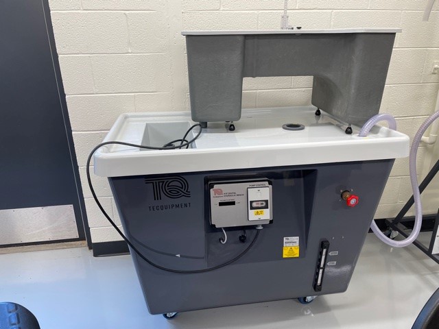
- H1F Digital Hydraulic Bench:
This fully mobile digital hydraulic bench supplies a controlled recirculating water supply to bench-mounted and free-standing experiment modules. It has an electronic flow meter and digital display for accurate measurements and quicker experiments.
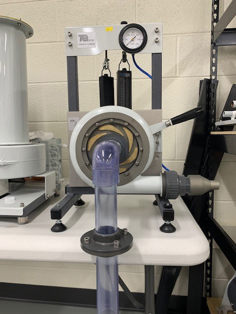
2. Francis Turbine:
The turbine has a sturdy base which sits on the top of the hydraulic bench. The turbine connects to the pumped supply of the hydraulic bench. The bench measures the flow rate. A mechanical gauge measures the inlet pressure to the turbine. Adjustable guide vanes in the turbine alter the flow rate and direction of flow to the impeller (runner) of the turbine. The end of the turbine outlet tube (draft) is in the open-water channel of the hydraulic bench.
Students test the turbine at different flow rates, loads and guide vane settings. They use the flow, torque, pressure and speed measurements to calculate hydraulic power input and mechanical (shaft) power at the turbine. They use these to create performance curves for the turbine.
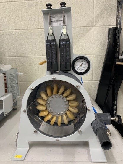
2. Pelton Turbine:
The unit consists of a Pelton wheel mounted in a corrosion-resistant enclosure. A transparent front panel allows students to see the turbine working. An adjustable spear valve directs a jet of water through a nozzle to the buckets of the Pelton wheel to make it turn. Manual adjustment of the spear valve controls the water jet from the nozzle. The turbine includes all pipes and fittings to connect it to H1F digital hydraulic bench. The hydraulic bench also measures flow rate. The Optical tachometer can measure the speed of rotation of the turbine. A simple mechanical brake and spring balance assembly attached to the shaft of the Pelton wheel applies a variable mechanical load (torque). A gauge measures inlet pressure.
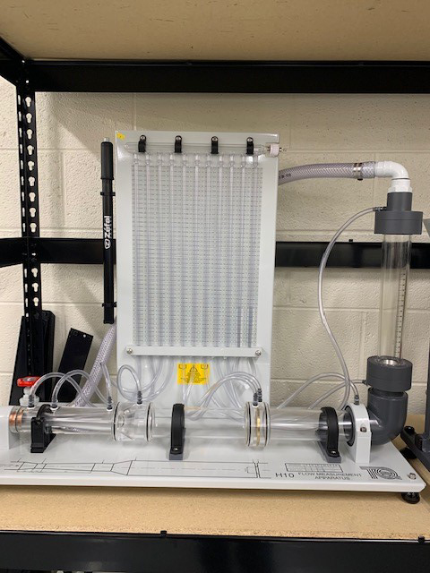
4. Flow Measurement Apparatus
Flow Measurement apparatus shows the typical methods of measuring the flow of an essentially incompressible fluid (water). It also shows applications of Bernoulli’s equation. Students measure flow using a Venturi meter, an orifice plate meter and a rotameter. Bernoulli’s equation works for each meter. Students find and compare the head losses for each meter. They also find the losses in a rapid enlargement and a 90-degree elbow. The apparatus is for use with H1F digital hydraulic bench.
The product has a horizontal pipe that includes a Venturi meter, orifice plate and pressure tappings. An elbow connects the pipe to a rotameter (gap-type flow meter) with further pressure tappings. All pressure tappings connect to manometers held on a vertical panel behind the pipe work. The manometers measure and show pressure distribution against a calibrated scale. To perform experiments, students connect the product to the hydraulic bench supply, and set it to a low, steady flow through the apparatus.
Water from the hydraulic bench then flows through the Venturi meter, through a sudden enlargement, a settling length and the orifice plate. It then flows around the elbow, through the rotameter, then a flow control valve, finally returning to the hydraulic bench. The control valve is downstream, so it does not cause any upstream turbulence.
Students measure the flow using the hydraulic bench, noting the manometer levels and rotameter reading. They then increase the flow in set increments, taking readings each time, until reaching maximum flow rate. They then use Bernoulli’s equation to find mass flow rate through each of the meters, comparing to flow rates measured using the hydraulic bench.
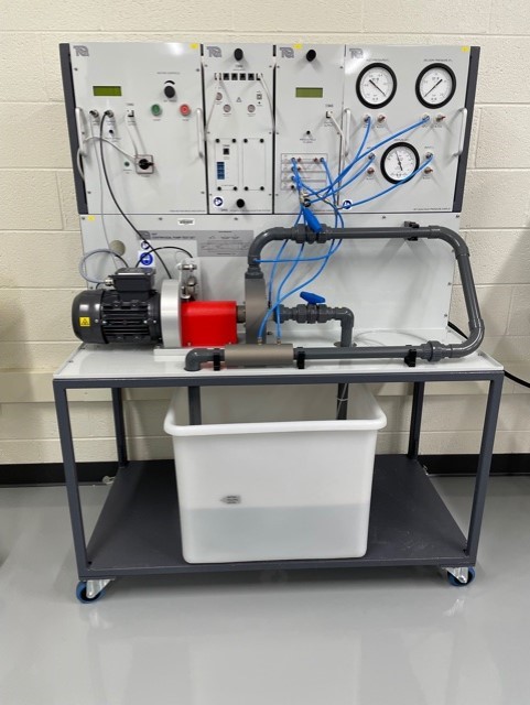
5. Centrifugal Pump Test Set
A compact, mobile and fully self-contained centrifugal pump test set that allows students to find the characteristics of a centrifugal pump. It also allows them to see (and hear) cavitation and understand the use of a Venturi meter and differential pressure measurement to find flow rate.
A motor mounted in bearings drives the pump. The pump draws water from the integral reservoir. The water travels up through a valve and filter, through an inlet valve to the pump body, then out through a delivery valve. It then passes through a Venturi meter and returns to the reservoir for re-use. This self-contained water supply keeps water consumption to a minimum. The pump has a transparent ‘window’ so students can see the impeller turning and how the water vapor bubbles form in the pump at cavitation. The optional stroboscope makes the effect easier to see.
An electronic Motor Drive controls the pump speed. A strain gauge load cell measures the driving torque of the pump and a sensor measures pump speed. A display on the Motor Drive shows speed and torque and automatically calculates and displays true ‘shaft’ power. The differential pressure across the Venturi gives flow rate. The adjustable inlet and delivery valves allow students to create different operating conditions.
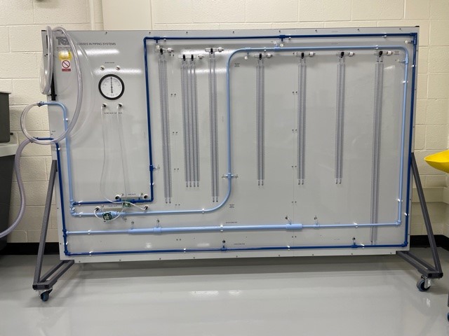
6. Losses in Piping System
The Losses in Piping Systems apparatus comprises a vertical panel with two separate hydraulic circuits, color coded for clarity. Each circuit includes various pipe system components. The unit has wheels for mobility. They also help when storing the apparatus. H1F digital hydraulic bench supplies each circuit with a controlled flow of water. This allows students to study flow through the various pipe forms and components, and study and compare the pipe and component characteristics.
To measure pressure loss across components, the panel includes piezometer tubes and a pressure gauge. The pressure gauge measures pressure loss across valves; the piezometer tubes measure pressure loss across the other components. Included is a hand-pump to adjust the datum position of the piezometers. Both circuits have common inlet and outlet pipes, controlled by valves. The valves are at the outlet to minimize flow disruption.
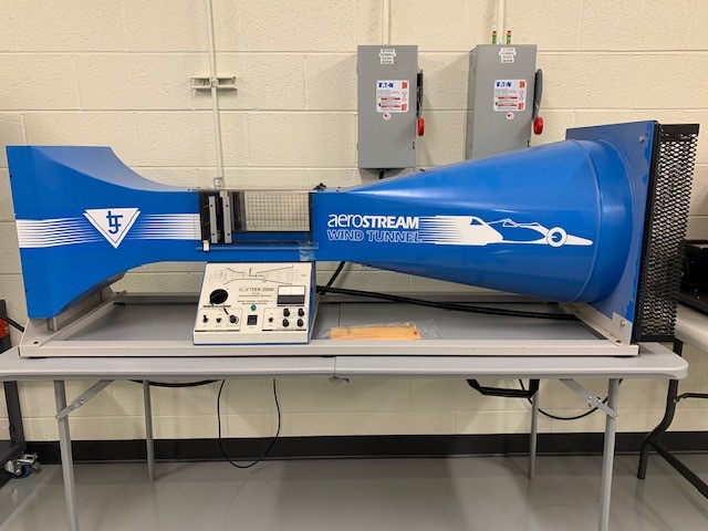
7. Wind Tunnel:
Is typically used for aerodynamic applications, such as control of a wind tunnel for measuring wind resistance. Users are able to explore the functions and controls of a real wind tunnel and identify how static and dynamic air pressure influences aerodynamics. Also used to experiment lift, down-force and drag aerodynamic forces.
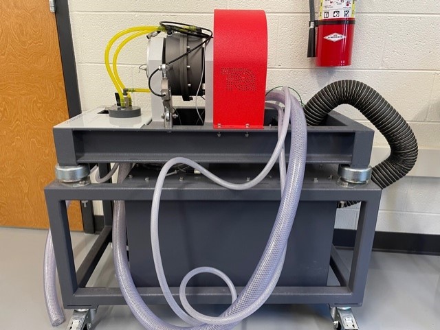
8. Small Engine Test Set
A versatile hydraulic engine test bed with comprehensive instrumentation. The equipment requires minimum services, installation and outlay. The equipment is fully compatible with Versatile Data Acquisition System (VDAS®). Using VDAS® enables accurate real-time data capture, monitoring and display, calculation and charting of all relevant parameters on a computer making tests quick and reliable.
The bed sits on a trolley for portability. It includes a robust, precision-machined, trunnion-mounted hydraulic dynamometer. A significant advantage of using a hydraulic dynamometer is that no large electrical supplies are required as the engine power is dissipated into the water used to load the dynamometer.
The dynamometer applies load according to the flow rate and level of water in the casing. An accurate needle valve controls the flow rate and level. An electronic load cell measures torque. The engines are supplied pre-mounted on a sturdy precision base plate. When the engine is initially mounted onto the test bed or exchanged with an alternative engine, dowels and slots locate the engine quickly, accurately and reliably.
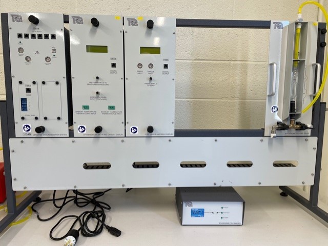
The instrumentation is mounted on a sturdy frame. The frame has a single power inlet and several power outlets to supply the various display units. The instrumentation and test bed are separate in order to avoid vibration being transmitted from the engine to the measuring devices.
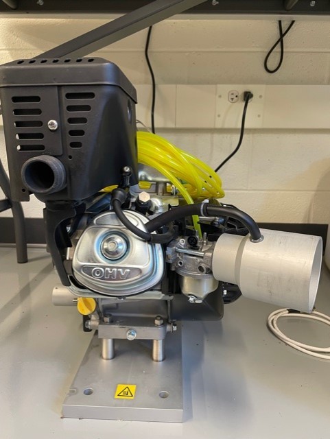
9. Four Stroke Petrol Engine
High-quality and cost-effective four-stroke, single-cylinder petrol engine for use with engine test set TD200. the engine includes an exhaust thermocouple, a half-coupling to link to the test set dynamometer and all essential hoses and fittings. In addition, each engine includes a color-coded fuel tank with self-sealing couplings.
The couplings ensure the engine can be connected and disconnected quickly and efficiently with minimum loss or spillage of fuel. For convenience and safety, the fuel tank can be removed for filling or for storage in a fuel locker when not in use
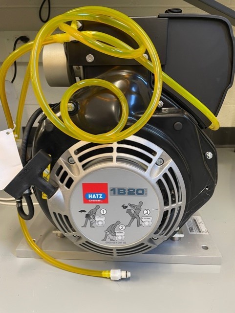
10. Four Stroke Diesel Engine
High-quality, cost-effective four-stroke, single-cylinder diesel engine for use with engine test set TD200. engine includes a color-coded fuel tank with self-sealing couplings. The couplings ensure the engine can be connected and disconnected quickly and efficiently with minimum loss or spillage of fuel.
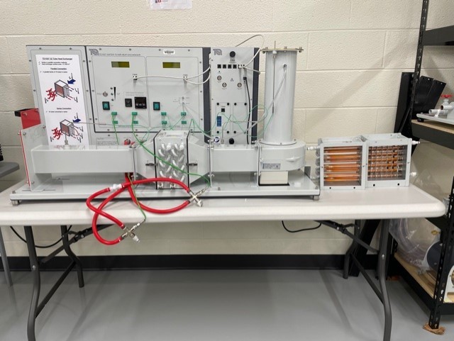
11. Heat Exchanger
An experimental unit to show how cross-flow water to air heat exchangers work. It fits on a bench top and includes a hot water supply, a cooling air duct and all instruments needed for tests on cross-flow heat exchangers.
It’s hot water system includes a tank with a PID controlled electric heater for stable temperatures, a pump and tank level indicators. A precision needle valve and flow meter control and measure the water flow rate. The cooling air passes down a vertical duct containing an orifice plate, which connects to a differential pressure transducer. The air then passes through a fixed speed centrifugal fan and along a horizontal duct containing the heat exchanger. The air exits the duct through a hand-operated slide valve.
Thermocouples at the water connectors and in the air duct measure hot and cold inlet and outlet fluid stream temperatures. Clear, multiline digital displays show the temperatures, water flow rate and orifice pressure (to calculate air flow).
The unit has two different heat exchangers as optional extras. One (TD1007a) has a single bank of 16 tubes, giving half the heat transfer area of the standard heat exchanger. The other (TD1007b) also has a single bank of 16 tubes, but includes fins to increase the heat transfer area to equal that of the standard 32 tube heat exchanger.
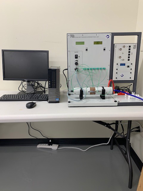
12. Linear Heat Conduction Experiment
Experiment that introduces the principles of linear heat conduction and thermal conductivity. This experiment has a solid brass bar of circular cross section, made in two sections with an interchangeable middle section. Each middle section has three thermocouples to enable the calculation of thermal conductivity of specimens.
Electrical Engineering Lab

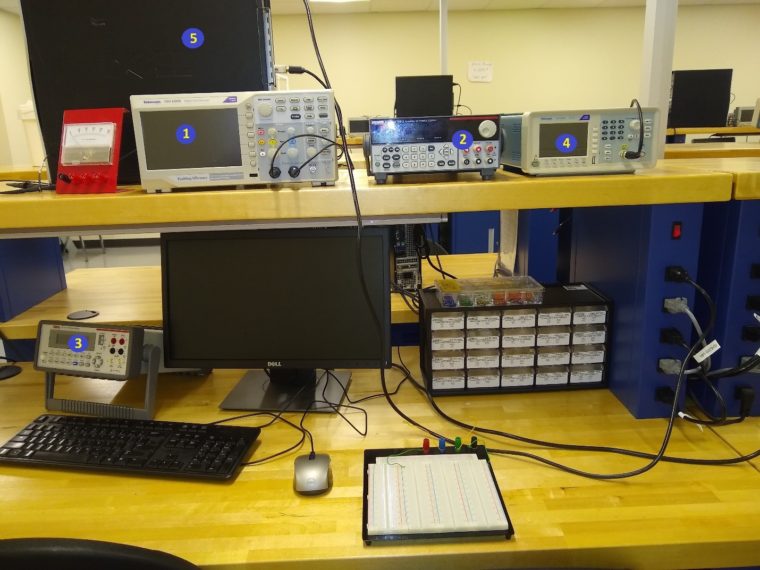
Equipment for ECE 2011 Circuit I Lab and ME 3023 Measurements in Mechanical Systems
- Tektronix TBS 1202B Oscilloscope
- Keithley 2231A-30-3 Triple Channel DC Power Supply (Note: one station has a BK Precision 1672 Triple Output DC Power Supply)
- Keithley 2110 5 ½ Digit Multimeter
- Tektronix AFG1062 Arbitrary Function Generator (Note: one station has a GW Instek AFG-2112)
- Windows 10 workstation (Microsoft Office, MATLAB, Multisim, and other software)
National Instruments SensorDaq – analog input/output device for computer data acquisition
Breadboard, assorted resistors, op-amps, cables, jumper wires, etc.
Engineering Computer Lab 015
Engineering Computer Lab 015:
Dell Precision Tower 3420
NVIDIA Quadro K1200 4GB, 4 mDP to DP adapter, Low Profile
3.5″ 1TB, (7,200 RPM) SATA Hard Drive
32GB (4X8GB) DDR4 2400MHz UDIM M Non-ECC
7th Gen Intel Core i7-7700 (Qu ad Core 3.6GHz, 4.2Ghz Turbo, 8MB, w/ HD Graphics 630)
Printers:
LaserJet CP5225
Engineering Classroom 016
Engineering Classroom 017